Showing posts with label Houdini Notebook. Show all posts

Thursday, March 22, 2012

The Copy Loop Technique

The Copy Loop Technique is useful for manipulating groups as if they were simple points or particles and want to avoid using DOPs if you don't need exact precision.

You can follow along with this example file:
copy_loop_example.hip


The method is broken down into 4 main steps:
  1. Create an ordered list of groups for each "piece".
  2. Create a single point at the center of each piece.
  3. Transform each piece to the global origin.
  4. Copy each piece back onto its corresponding point.

Creating Groups


The first step is key. Say you have created a fractured model using the Voronoi node. You end up with an ordered list of primitive groups, going from 0 to n. When you hold MMB onto the node you can see your group list. (If needed, you can right-click and choose "Extended Information" to see all primitive groups). Before you continue, the list of groups must be in order and no skipping; meaning that they need a common prefix, such as "piece", be in order from top to bottom, and have no missing or empty groups.

You can also use the old Connectivity to Partition combo.


NOTE: In Houdini 12, the list doesn't have to be in order from top to bottom, but should still have a common prefix and not have missing groups.


Creating Center Points


Loop for each piece

The next step is simple. Just use a ForEach SOP and for each "piece", create a center point using an Add SOP and the centroid() expression.

Inside the point ForEach

The Add SOP can just hang on the side as long as it is displayed. You don't need to connect it to anything.

Points created at center of each piece


Centering All Pieces


The third step will go into a different branch from your primitive groups. You need to move each group to global origin. You can use another ForEach and inside, use a Transform SOP.

Inside the center ForEach

The Transform SOP has -$GCX, -$GCY, -$GCZ in its xyz translate parameters.

Centered pieces


The Copy Loop


The last step is a little hard to grasp the first time you see it. What will happen is this:
  • You take your centered pieces.
  • Isolate all but one piece.
  • Copy that piece to its corresponding point.
  • Repeat those steps for each piece.
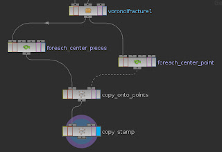
The key that makes this work is copy stamping using the Copy SOP. You will need 2 Copy SOPs, one to place the piece onto the point, and one to stamp, or loop, the action for every piece. 
The final layout

As a simple example, say you have a Sphere, a Mountain, then a Copy and create 5 copies. Normally each copy will look the same. But if you want each copy to have an offset in the noise, you can use stamping. Check "Stamp Inputs" and create a custom variable, anything you want. Then set that value to $CY, which represents the copy number. Now go back up to the Mountain and use the stamp() expression one of the offset parameters.

So what you are doing is sending information back up the network and it reflects back to the copy step.

So back to the main event, we will use the same Copy node with $CY, along with another Copy node before it that places the pieces onto the points. We will use the stamp() expression in the Source Group and Template Group parameters.

stamp("../copy_stamp", mystamp, 0)

piece0 gets copied to point 0, piece1 gets copied to point 1, etc.

For convenience, we can set the number of copies, or loops, to ensure we are including all of the pieces or not over-copying by using a combination of the argc() and primgroupmask() expressions.

So now that we have this set up, we can now manipulate the center points to affect the pieces. Convert them to particles, add some animated noise expression, change normal direction, add color or pscale, whatever...

Sometimes you may need to set your normals and upvectors to the points depending on the situation.

Wednesday, December 14, 2011

Platonic Solids and Duality

I recently came across a post on odForce about hexagonal meshes. After searching info on this subject, I came across the concept of polyhedrons. This stuff is pretty interesting. Polyhedron in Greek means "many faces", so its just a 3-dimensional shape with many faces. There are special polyhedrons called Platonic Solids.


The image above are the 5 Platonic Solids and their "duals". Only 5 of them exist. All angles in these special polyhedrons have equal faces, angles, and edge lengths.
The dual is when you change each vertex to a face. And when this happens on a platonic solid, the number of points and primitives gets swapped.

In Houdini, just use a Platonic Solids SOP to get them.


The last two types, Soccer Ball and Utah Teapot, are technically not platonic, but they have been used so much in computer graphics, that they have become adopted!

To get the dual, use a Divide SOP with "Convex Polygons" unchecked and "Compute Dual" checked.

If you go to Wikipedia, and search polyhedron or platonic solids, you can get alot deeper than this.

Anyway, to the hexagonal mesh thing, here is a way to do it. Take a grid, then use a PolyBevel SOP with "Relative Inset" set to 1, then the Divide SOP with Compute Dual and keep Convex Polygons checked.

You end up with a nice honeycomb shape! You can then go further and use PolyWire, PolyExtrude, etc. and do some neat things with it.

Friday, June 24, 2011

Houdini Notebook #4: OBJ Files Across Maya and Houdini

Importing and exporting OBJ files is pretty easy. In this notebook, I just want to go into more detail about using them across the two softwares.

Maya to Houdini

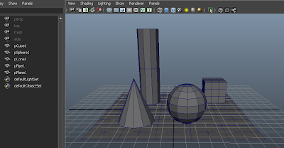
Lets take this Maya scene of five objects. I could export each object into separate OBJ files. But say this is a character and I would like it to be just one file.

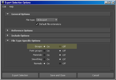
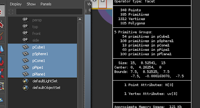
If I select all of the objects and go to the export dialogue, I can check on 'Groups'. This will let the OBJ data to recognize that there are 5 "groups" in this geometry.

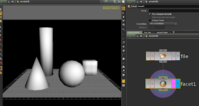
When we bring in the file in Houdini, sometimes the normals will turn out strange. To fix that, just use a Facet SOP, and 'Pre-Compute Normals' checked. Now if we take a look at the information...

...we see that we have 5 primitive groups with the same names as the objects in Maya. We also have the UV information coming in as a Vertex attribute, so that's useful. Geometry coming from Maya usually comes with Normal and UV data embedded. Groups created in Maya will also appear in the list.

Houdini to Maya

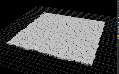
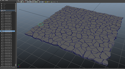
Here is a ground chunk model I created in Houdini. Before exporting this geometry as OBJ, we should first prepare the data we want embedded in the file.

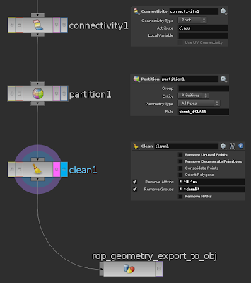
I need to create primitive groups for each of the chunks. Depending on the model's topology, the methods may vary. For this one, I can just use a Connectivity SOP to Partition SOP.

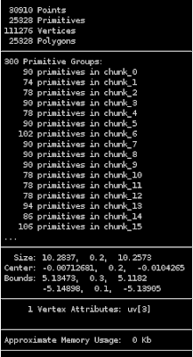
Next, it is a good idea to clean out unnecessary attributes. This will help keep the OBJ's file size to a minimum. Besides, Maya cannot use data such as point color and point velocity. The Clean SOP is a convenient way to do this. Just remove everything but the Normal and UV attributes. Make sure that the UV attribute is a Vertex type attribute and not a Point type.

Also clean out unused groups. Make sure that, one, they are Primitive type groups and not Point type. And, two, that no primitives are a member to more than one group. Maya doesn't like that too much.

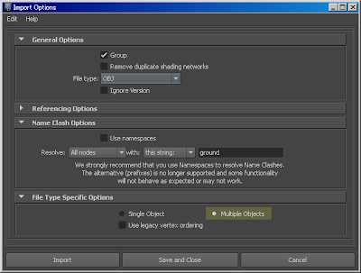
Now in Maya's Import Options menu, check 'Multiple Objects' so that each group you created in Houdini will come in as a separate object. The other stuff in the menu is optional.

There you go. Sometimes the edges come in hard. You can just use Maya's Soften Edge function to fix that.

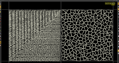
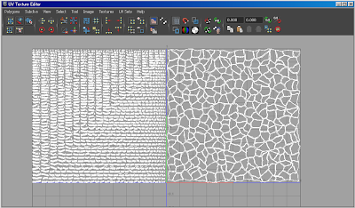
Our UVs came in OK too.

What if you have animation? What if your UVs change over time? Well that's another story. For now I just wanted to focus on OBJ files in general.

Friday, June 10, 2011

Houdini Notebook #3: Camera Clipping Points/Particles

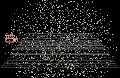
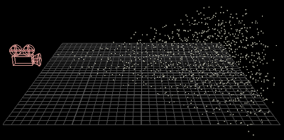
Here is a neat trick that will clip points or particles that are not seen through the camera. Note that this will not work well with geometry.

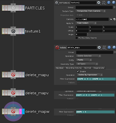
After your particles, use a UV Texture SOP and set it to 'Perspective From Camera'. Enter the camera you are using. This will create a uv[3] point attribute onto the particles. In the field of view of the camera, u is the horizontal, v is the vertical, and w is the depth. u and v range from 0 to 1, while w is the distance from the camera.

So after that, just use the Delete SOP and use $MAPU, $MAPV, and $MAPW to delete the range of uv values.

If you use 'Near Clipping' and 'Far Clipping' on the camera, the u, v, and w values of points that lay outside of the clip will be 0.

So before you copy objects on the particles, or add a particle fluid surface, you can use this trick to clip out the points you don't see in frame. This could avoid tons of unneeded calculations. But be careful if you have shadows or reflections, this might result in some popping.

You could also pad the deletion to be safe, say:
$MAPU <= -0.5 || $MAPU >= 1.5

Or maybe instead of just deleting the points, you could reduce detail or something.

Here is a Digital Asset that does all of this:
Download [ sop_cameraclip.otl ]

Thursday, June 9, 2011

Houdini Notebook #2: SOP Attributes to DOPs

You can easily use attributes that you created in SOPs in DOPs by using the point( ) or prim( ) expressions. In DOPs, the syntax is, for example:

point( $OBJID, 0, "Cd", 0)

Here I am grouping the pieces of the fractured object by primitive color:

Here I am using a Velocity Impulse Force DOP to give a sudden push in velocity at frame 30. In SOPs, I created a vector attribute called impulse.

If your attribute values change over time, you can check 'Use Deforming Geometry' in the DOP object nodes or use a SOP Solver to update the attributes every frame.

Wednesday, June 8, 2011

Houdini Notebook #1: Vectors Along a Curve

Ever need a vector attribute that runs along a curve? Maybe you want to use it as a force for particle movement or FLIP fluids. Here are a few easy ways to do it.

One of the most underused and badly named SOPs in Houdini, the Polyframe SOP. If used on a curve, this will create a tangent attribute along the u coordinate. By default, this attribute is named tangentu, but you can just enter something more commonly used for effects, like N or v.


You can also use a Point SOP, go to the Force tab, and check on Add Edge Force. The vector point attribute created is called edge_dir. You can later remap this to N or v.

If you need to reverse the direction of the vectors, just use a Reverse SOP before doing these procedures.